


Submodeling Technique from Beam to Shell5 Septembrie 2022
Submodeling, as the name suggests, is the modeling of a portion of a global model to capture the effects of refined mesh in a smaller model. This is done to avoid having the whole assembly meshed with fine elements.
ANSYS Mechanical allows submodeling for structural (stress) and thermal analyses. In a thermal analysis, the temperatures calculated on the cut boundary of the coarse model are specified as boundary conditions for the submodel.
Benefits
Aside from the obvious benefit of yielding more accurate results in a region of your model, the submodeling technique has also other advantages:
- It reduces, or even eliminates, the need for complicated transition regions in solid finite element models.
- It enables the user to experiment different designs for the region of interest (different fillet radii, for example).
- It helps demonstrating the adequacy of mesh refinements.
Types of transfer
- Shell - Shell
- Solid - Solid
- Shell - Solid
- Beam - Shell/Solid
We are presenting here an example for the last mentioned type of transfer case, in which the large (global model) is meshed with beam elements and the local one uses shells.
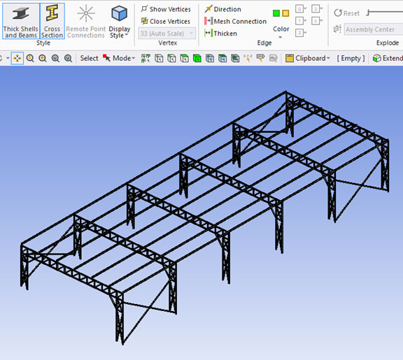
The structure is an industrial hall. It is modeled with beam elements. The program allows a visualization of the defined crossed sections.
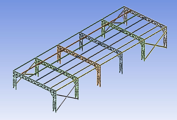

The structure is checked for ultimate limit state against earthquake, snow and wind load. Let`s consider that the wind loads are frequent and high and fatigue for welds might be an issue. In this case the weld assessment must be performed using a recognized standard. We did the analysis considering the standard IIW - RECOMMENDATIONS FOR FATIGUE DESIGN OF WELDED JOINTS AND COMPONENTS from 2008. The analysis can be performed using shell or solid elements.
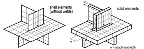
Typical meshes and stress evaluations paths for a welded detail (IIW standard)
The stresses for the given wind load are obtained and the area where issues are expected is presented. The fatigue cycle is defined as being between zero and a specified wind load. This is a simplified approach. Usually, a rainflow count must be performed and the final damage is to be computed using Miner`s rule.
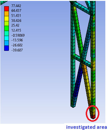
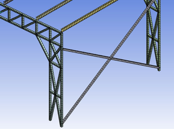
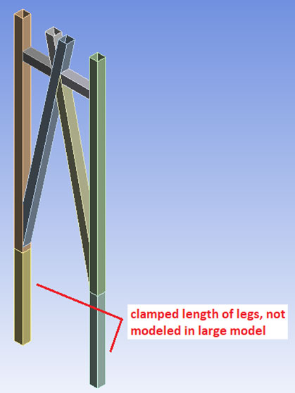
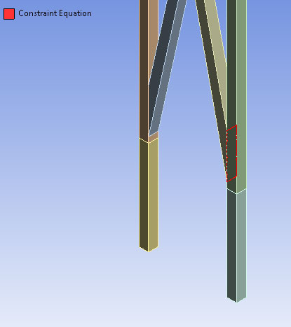
We can see in the above picture the third supporting leg of the hall from the wind loaded side. A submodel with cuts away enough from the investigated area is created using shell elements.
There are recommendations regarding the mesh size for the submodel given in the IIW standard. We classified the investigated weld as a Type b and used shells with 4x4 mm size.
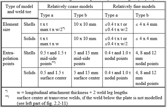
Recommended meshing and extrapolation (IIW standard)
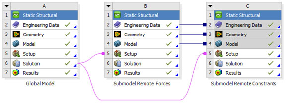
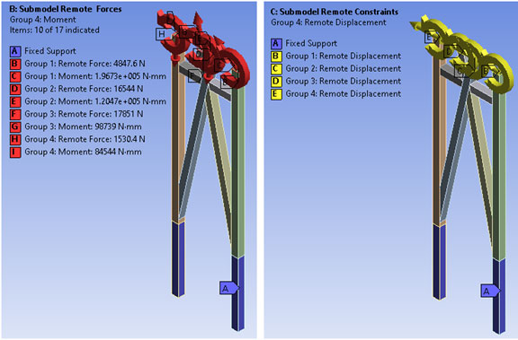
The submodel can be loaded with imposed remote forces or constraints on the defined cuts.
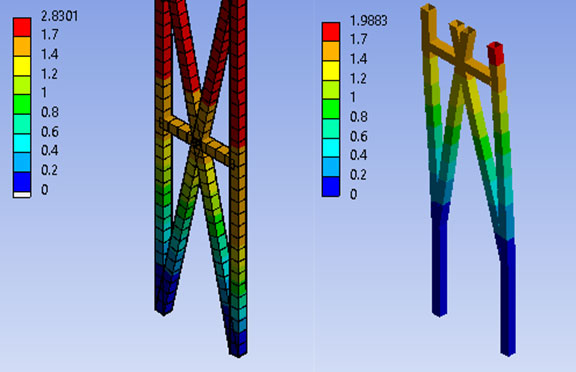
The following picture presents the comparison between total deformation field for large model (left) and submodel (right). Please notice that in the submodel the clamped region in concrete for the legs is added. The correlation is quite good.
The contact defining the studied weld is formulated as MPC with a pinball radius of 3 mm (thickness of the plate).
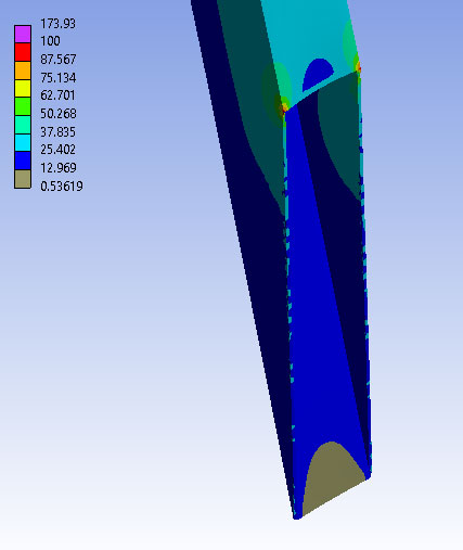
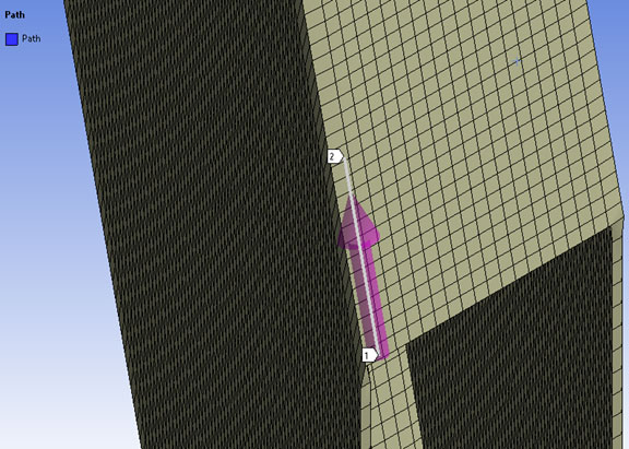
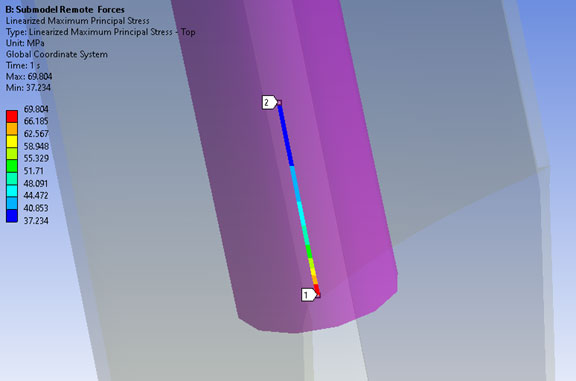
The maximum principal stress is plotted. It can be observed that the maximum stresses in the weld area are in the lateral edges. So, a path is defined in order to visualize and extract the values.
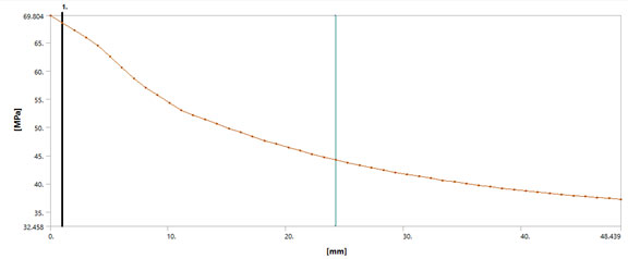
The value of the principal stress at the weld toe is obtained by interpolation for type b hotspot according to IIW standard. Evaluation is performed at three reference points 4 mm, 8 mm and 12 mm and using the following quadratic extrapolation:
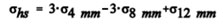
Extrapolation expression from IIW standard
We are obtaining a value of 71 MPa for the hotspot. Then, according to recommendations from the IIW standard, we use FAT 100 category (FATx: classification reference to S-N curve, in which x is the stress range in MPa at 2 million cycles). Next, using the recommended fatigue curve we determine the lifetime of the weld as being 2.79e6 cycles. The value is lower than the endurance limit of 1e7 cycles.
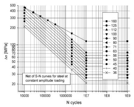
Fatigue resistance S-N curves for steel, normal stress, standard applications (IIW standard)
Conclusions:
- ANSYS provides very strong tools to perform submodeling;
- In this example, the geometry is imposing the usage of beam elements for the global (large) model. It is possible to model the large structure with shells, but it would be very time consuming;
- The automatic transfer of the remote forces or constraints between models works fine, the differences in the displacement field are minimum;
- In this example the studied weld is above endurance limit, so it has a finite life. According to the design requests, it can be acceptable or it might require lowering of the stresses in that area;
- Using only the beam model, such a detailed analysis is not possible. There are cases where usage of submodels is a must in order to wisely consume hardware and time resources.