Structural Optimization Analysis16 August 2022
How to get clean CAD Geometries and Optimized Design Checking
The new topologies that are obtained in a topology optimization simulation cannot be used directly. They must be transformed in CAD geometries. We present below how to reverse engineering the optimized component using any of the four methods available in ANSYS Mechanical.
There is one approach for lattice optimization and a common one for the other three methods. We begin with the lattice optimization.
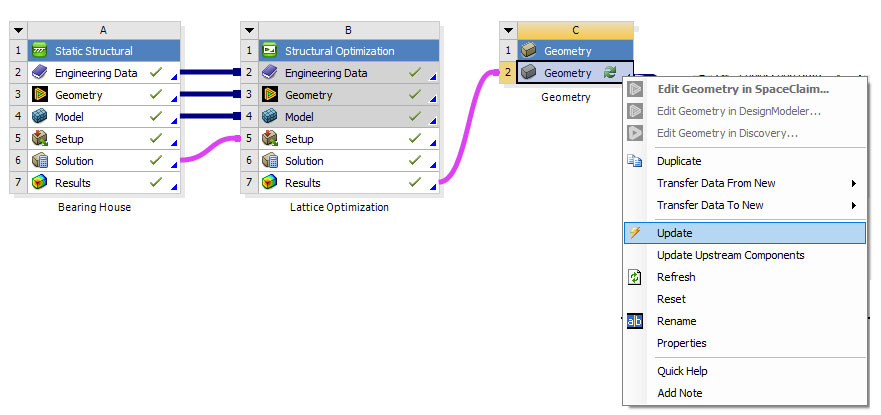
The results must be transferred to a geometry box. After update the geometry must be opened with ANSYS SpaceClaim.

The Shell command is to be used with Use density attributes from the Basic type.
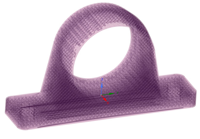
After setting transparency style we can see the internal lattice structure.
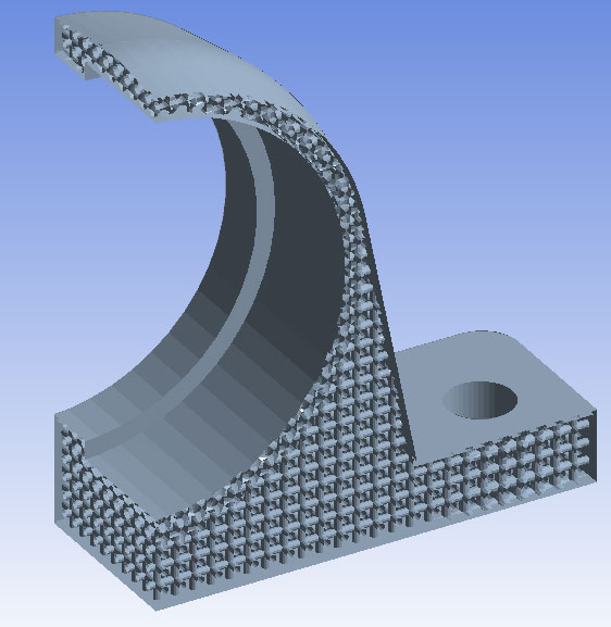
In ANSYS Mechanical we are able to see better using section planes.
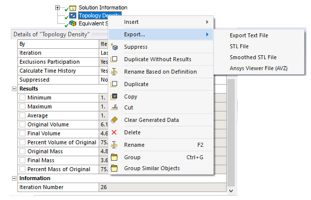
Now, for the other three methods, the optimized geometry can be exported as STL file.
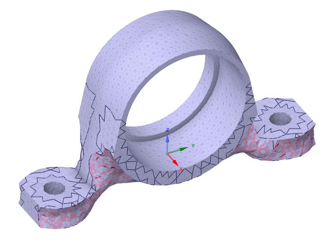
Using SpaceClaim the STL file is converted in a CAD geometry. The imported STL file looks like this.
In the following pictures there are detailed steps done for the STL file corresponding to Level Set Optimization.
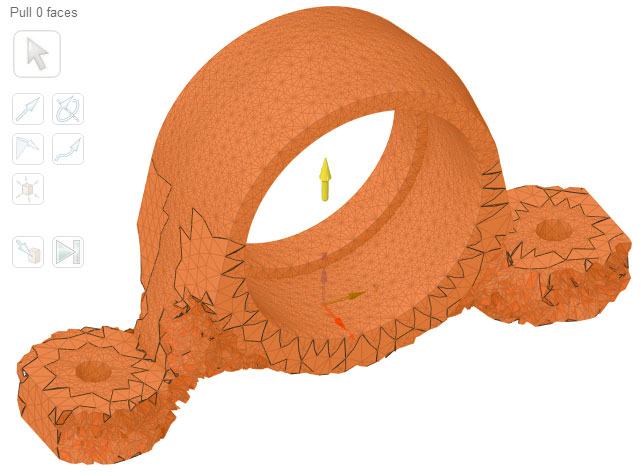
The body is going to be wrapped and smoothed, so it is a good idea to enlarge it using Pull command.
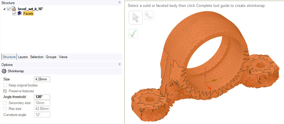
A Shrinkwrap operation can be performed. The settings regarding Angle Threshold and option to Preserve features are problem dependent. There is no universal methodology.
Then a Smooth operation can be deployed.
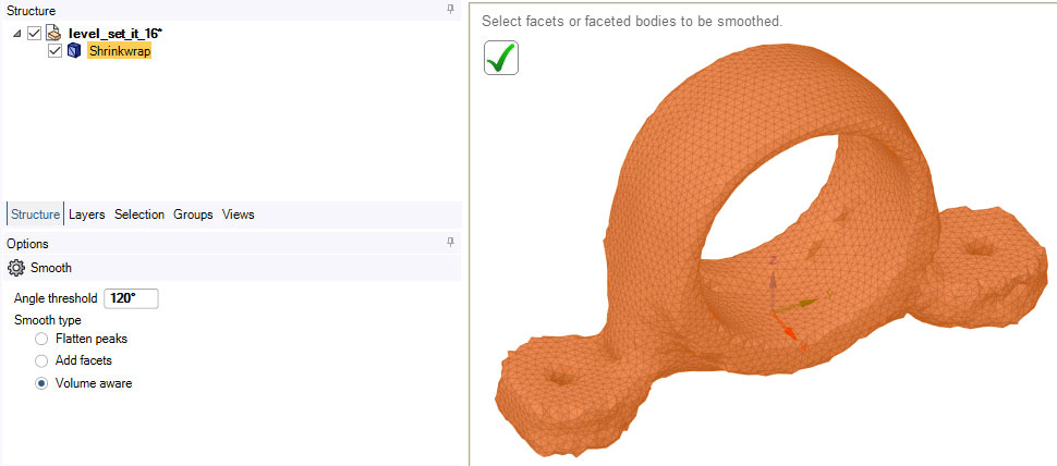
Again, the options that are used for the smooth operation are problem dependent.
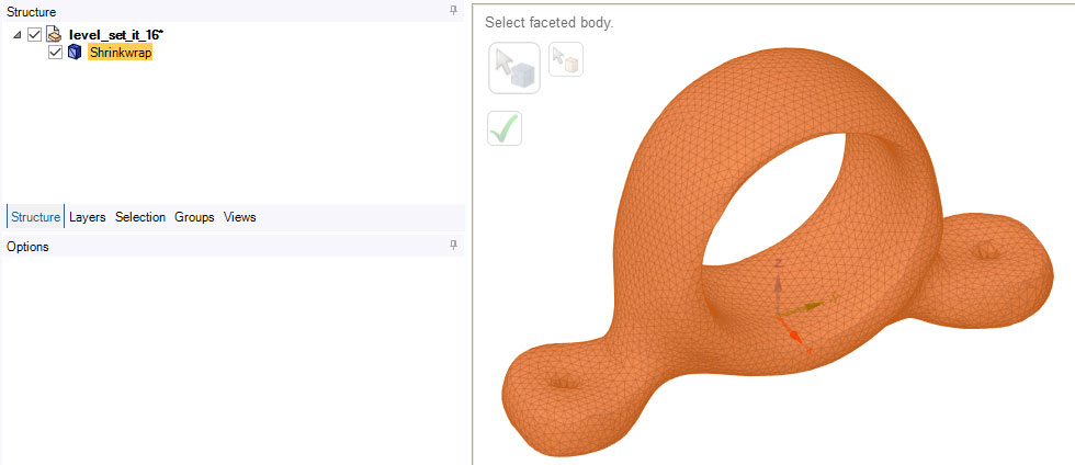
Finally, AutoSkin command is used and we get the CAD geometry.
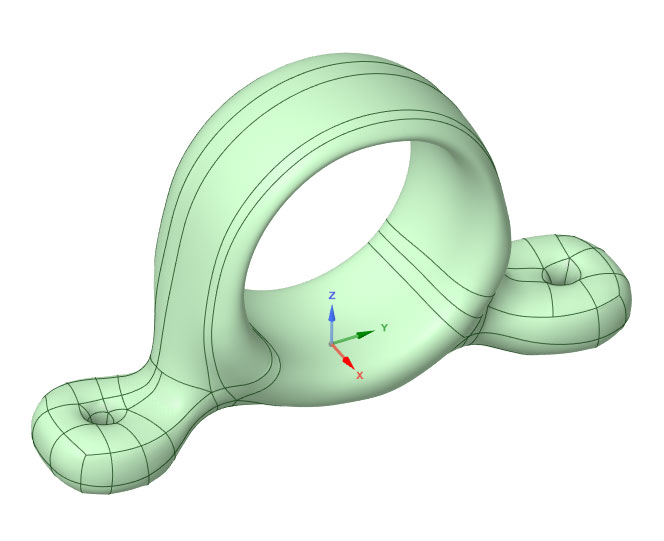
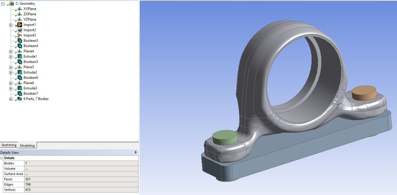
It is obvious that this shape is not preserving the dimensions for the holes of the bolts, the location of the shaft/bearing plus the connection surface to the plate. Also, the faces are defined in such a way that boundary conditions cannot be applied directly.
This can be managed by using Boolean operations (intersection with the plate, remove material using the bolts, fill the shaft/bearing hole and drill to the right dimensions).
ANSYS SpaceClaim or ANSYS DesignModeler can be used for these operations. In this example we have been used ANSYS DesignModeler.
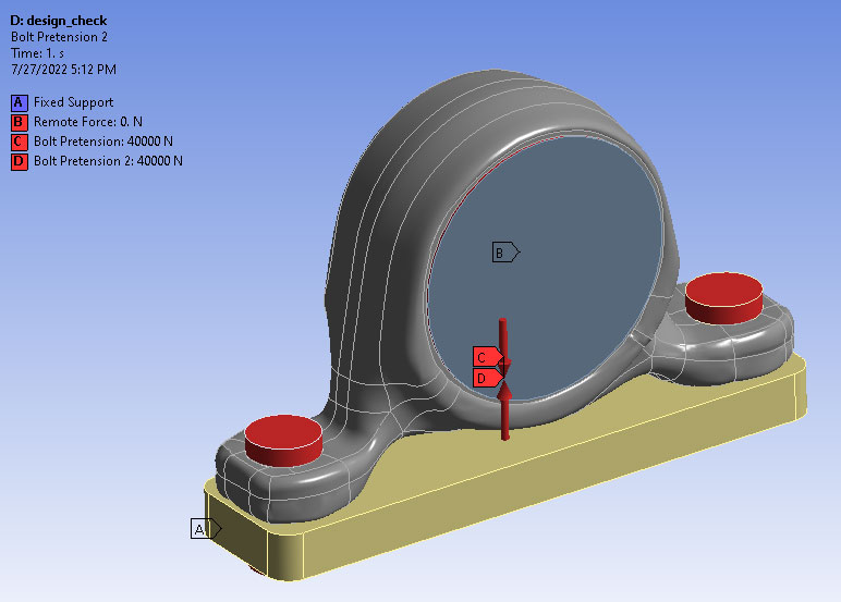
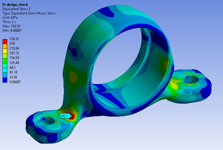
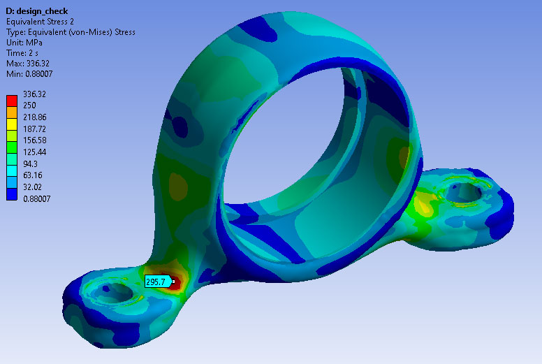
For the worst load case scenario we get a very small area where the limit of 250 Mpa for the equivalent stress is exceeded. All the imposed displacements are in limits.
What are the next steps in this case?
We can adjust the fillet radius in ANSYS SpaceClaim, or we can smooth more or inflate more at the beginning of reverse engineering process, or to consider the STL file of an earlier iteration (which has a lower mass reduction). There is no standard procedure, this is problem dependent.
Conclusions:
- ANSYS SpaceClaim should be used to obtain valid CAD geometries based on the stl files generated by ANSYS Mechanical;
- The CAD file that we obtain is not 100% accurate and it must be corrected to fit the original assembly conditions. Special attention must be paid in order to have the faces correctly defined so that to correctly apply necessary boundary conditions for the final simulation (checking that all conditions are satisfied);
- Not always the last valid optimization iteration from ANSYS Mechanical is passing the final check and the whole process is reiterated till we get the desired result.


